Normally, I don't spend much time factoring in the amount of carbon generated by manufacturing something that I'm going to use for carbon mitigation when figuring out how much carbon it will reduce. My reason is that we have to use the carbon-based technology we have to build the carbon-free society we want. Most calculations I've seen for, say, the amount of carbon generated by manufacturing solar panels v.s. the carbon they save over their 30 year lifetime indicate that the scales are heavily weighted towards massive savings in carbon emissions for solar cells. Even renewable energy sources with marginal carbon saving, such as corn-based ethanol, have become more efficient over the past 5 years. If you don't take indirect carbon into account - the amount of carbon generated by land that is put into production to make up for the land devoted to corn for ethanol - there is a savings, though not much. Indirect carbon accounting is controversial, however. If the same accounting method were used for other technologies, for example, the carbon generated by nickel mining to make up for the nickel that goes into a Prius battery, almost any technology would come out losing in the end. The people who came up with indirect carbon accounting were just looking for an argument against corn ethanol because they don't like the idea of trading off food for fuel with the population still headed upwards, and I agree totally. There are plenty of other ways to achieve a carbon free transportation network which don't involve that tradeoff, and we would be pursuing them more forcefully if it weren't for politics.
But a couple of nights ago, I came up hard against this issue of global warming gas emissions from technologies that are good at reducing energy use and thereby carbon emissions. I'm not talking about carbon here, but rather HFCs. HFCs are gases containing fluorine, carbon, and hydrogen that are used most commonly in refrigerators and air conditioners. They replaced CFCs after the Montreal Convention was passed, because CFCs were causing reductions in the ozone layer, an even more serious - but now thankfully receeding - environmental problem than global warming. HFCs have no impact on ozone but they are a global warming gas. Their impact on global warming can be many thousands of times as powerful as carbon dioxide. On the positive side, they do not remain in the atmosphere very long, around 7-10 years, unlike carbon dioxide which has a atmospheric lifetime of around 450 years.
I was interested in what impact our spray foam insulation might have so I sent email to Paul asking what product Ponzini used for their closed cell spray foam. As usual, he didn't reply so I checked Ponzini's web site and found a link to the product, Johns Manvill Corbond III SPF. I had done some research before on spray foam, and there are some green products out there, advertised as made from recycled plastic and soy oil, like Demlec. I had used Demlec in a previous open cell foam job to seal the wall between the attic/garage and the house. JM's Corbond doesn't appear to use soy oil, it's petroleum based, but, as mentioned above, using food crops for nonfood applications has some powerful arguments against it. JM's Corbond claims around 16% recycled content, that is about what Demlec claims too, even though JM doesn't make a big deal about being a green manufacturer. Quite to the contrary, their page on sustainability is filled with a lot of high minded rhetoric, but when you look at the pages on their products the information on ecological effects, such as about recycled content, is buried deep in the data sheets (for example, this data sheet on the B component of Corbond). Demlec, on the other hand, calls out this information in a completely separate page. Both Demlec and JM Corbond use HFC 245fa, a powerful global warming gas, as the blowing agent to blow small bubbles into the foam. So if you drill down on it, the only real difference between a "green" product such as Demlec and JM Corbond is the fact that the green product uses soy oil instead of a petroleum derivative.
I should say something about spray foam insulation here (unfortunately, there's no good Wikipedia page on this). Spray foam insulation comes in two basic types: open cell and closed cell. Open cell foam has a R-value about the same as fiberglass batt, R-3/R-4 per inch, while closed cell foam has a much higher R-value, R-6 per inch. Closed cell foam is the "gold standard" in insulation. Only aerogel does better, at R-10 per inch, it is the platinum standard. "Platinum" and "gold" here refer not just to their insulation potential but also to their cost. Spray foam, even open cell spray foam, is about 2-3x as expensive as fiberglass batt, while aerogel is completely unaffordable except for very limited applications such as my planned thermal bridging treatment. Both closed cell and open cell foam reduce air penetration, unlike fiberglass batt, but open cell foam is permeable to moisture while closed cell foam tightly seals against it, thereby acting as a vapor barrier.
The kind of foam insulation that we are having installed is polyurethane, a commonly available product used not only in home insulation but also for insulating refrigerators, hot tubs, coolers, etc. Prior to installation, polyurethane spray foam comes as two separate liquids, an A component and a B component. The A component contains a mixture of isocyanates while the B component is primarily a polyol with some other chemicals. When the two components combine, the two chemicals react to form polyurethane plastic. A blowing agent pushes the two chemicals together and expands to form tiny bubbles in the plastic. The tiny bubbles give the plastic its insulation value. Depending on the blowing agent, the result is either soft open cell foam or rigid closed cell foam. If the blowing agent is water, the result is open cell foam because the water reacts with the chemicals to form carbon dioxide, which expands rapidly resulting in a less dense foam with less insulation value. If, however, closed cell foam is desired, the blowing agent is HFC245fa. HFC245fa expands more slowly than carbon dioxide so the bubbles are smaller. But both types of spray foam insulation generate green house gases, however closed cell foam generates a gas, HFC245fa, with 1000 times the greenhouse gas potential of carbon dioxide.
The fact that the insulation would result in greenhouse gas emissions was, of course, somewhat depressing since the whole point of this work is to eliminate greenhouse gas emissions. However, as pointed out in this article, the net impact depends on how much global warming gas emission is eliminated by the treatment over the lifetime of the product. So I went about calculating what the rough impact was of the global warming gas emissions v.s. the amount of gas eliminated. I took the crude architectural model of the house I created a few years ago and measured the depth of the studs in all areas so I could calculate the volume of the foam that would be blown into the stud bays. For the floor, I estimated the area as 2500 square feet. Then I calculated out the volume of foam, correcting for the volume of the walls, floor and ceiling that are structural members, as described in the thermal bridging post. I came up with a volume of 1435 cubic feet, or around 1500 cubic feet. This is probably a bit high but should be a good enough estimate.
Closed cell foam has a density of 2 lb/cubic foot. This gave me the weight of the foam, around 3000 lbs. Of that, half is the B resin which contains HFC 245fa, or around 1500 lbs. HFC 245fa makes up between 7-12% of the B resin fraction. Taking the higher number, the amount of HFC 245fa released should be around 180 lbs. Since HFC 245fa has a global warming potential around 1000x carbon dioxide, this would amount to around 180,000 lbs, or 90 English tons, of carbon dioxide. Then comes the question: how much carbon dioxide will be eliminated? That is harder to calculate, but I've estimated that R-6 per inch foam insulation in our walls should reduce gas usage by around 30%. Using that as the figure, the insulation should eliminate 106 therms/year of gas. At 11.7 pounds of carbon per therm, that's 2907 lbs of carbon per year, or around 3000 lbs rounding up. So it will take 60 years for the house to break even from the HFC245fa released during the insulation.This was truly distressing. Here I am trying to do the right thing and reduce the carbon footprint by making my house energy efficient and the technology I've used will take 60 years before there is breakeven in the carbon emitted by the insulation!
So what were the alternatives? We had originally planned to install a geothermal heat pump with blown cellulose insulation in the walls and spray foam only in the ceilings and the floor. Geothermal heat pumps use HFCs too, and can leak them slowly out in the atmosphere, but not as much as spray foam. But the geothermal heat pump turned out to be too expensive and too complex. We could have continued with blown cellulose, but it does not achieve an air barrier and is therefore much less effective than spray foam. It is possible to make a house air tight with blown cellulose, but it requires going over the entire house and sealing up all the cracks in the siding. In addition, most newer houses have complicated vapor barriers on the exterior between the siding and plywood sheathing. Our house has no plywood sheathing, there is just the exterior plywood siding and the interior drywall, with a thin layer of tar paper under the siding. This is a rather poor vapor barrier, even in California's Mediterranean climate. So the spray foam should give us a much better vapor barrier. Blown cellulose also has a tendency to sag over time, and completely loses its insulation value if it becomes wet. Finally, spray foam increases the structure integrity of the building envelope, an important factor when considering earthquake.
So having foam insulation has some really desirable properties which we don't want to give up. In a situation like this, my feeling is the best solution is to pay for carbon offsets. It's like flying, in some cases there are alternatives to flying (taking a train or driving for example) but they are often impractical. We offset our our familial carbon emissions for housing and transportation every year anyway. We use carbonfund.org, a nonprofit, which means our carbon offsets are tax deductible. As it turns out, the carbon emissions from our insulation job should be about what a family of 4 in the US emits in one year, which in and of itself is kind of sobering. The cost at $0.004/lb is around $810. So next year, after the insulation job is finished, I plan to send a check to carbonfund.org for the carbon offsets. Carbonfund.org lets you select the type of offset, so I'll select forestry to establish a long lasting sink for carbon that will span the 60 years that I hope our house will still be around (though of course I'll be long gone).
I've asked Paul to get the amount of the B resin used by Ponzini so I can refine the estimate, and I will report on the exact amount when I have it.
Sunday, December 26, 2010
Thursday, December 23, 2010
Yet More Drywall Removal
Last week, I suddenly realized that we might not actually have all the drywall removed from the thermal envelope. The front of the front upstairs bedroom sticks out slightly from the plane of the house, like a dormer. You can see it in this photo below:
 This is about a two foot section where the bedroom has an exterior wall rather than sharing it with the attic.
When I went upstairs to check, sure enough, the drywall was still on. So the drywall removers had to come yet again. Here's what it looked like on the west wall when they were finished:
 The round white target shaped thing on the top is the HRV vent.
Sigh. Hopefully, this will be the very last time we will need to have the drywall removers here, because Ponzini has started doing the insulation underneath the house.

When I went upstairs to check, sure enough, the drywall was still on. So the drywall removers had to come yet again. Here's what it looked like on the west wall when they were finished:

Sigh. Hopefully, this will be the very last time we will need to have the drywall removers here, because Ponzini has started doing the insulation underneath the house.
Wednesday, December 22, 2010
Thermablok and Thermal Bridging
While mold most often occurs where there are roof or siding leaks, it also occurs when warm, moist air contacts cold structural members, causing water to condense out. We found mold on the face of a stud in the south hallway wall. The south hallway wall receives no sun in winter so the outside wall doesn't warm up during the day and, as a result, likely gets much colder at night. When mold occurs on a stud and there is no evidence of any siding leakage (as in this particular case) it is probably a result of thermal bridging. Insulation won't help because it is installed between the studs, and it won't stop heat transfer through the face.
I discussed thermal bridging in this previous post. The conclusion was that it would be too expensive and difficult to treat the whole house for thermal bridging, besides which, the insulation and drywall contractors probably wouldn't know what to do. However, I do want to treat the south wall of the hallway, to eliminate the condensation problem. So I ordered 50 strips of Thermablok , which I described in my previous post, enough to face the studs on the south hallway wall. Thermablok is an aerogel insulation that comes in 4' by 1.5" strips. The back of the strip has adhesive on it. Installing it couldn't be easier: you peel off the plastic strip and paste it onto the face of the stud (making sure of course there is no drywall dust or other dirt on the stud to clog up the adhesive). Aerogel is the most effective insulating material after vacuum, at around R-10/inch. These strips will add R-4 to the studs, effectively doubling the insulating value of a 2x4. But aerogel isn't cheap, the strips are about $4 apiece.
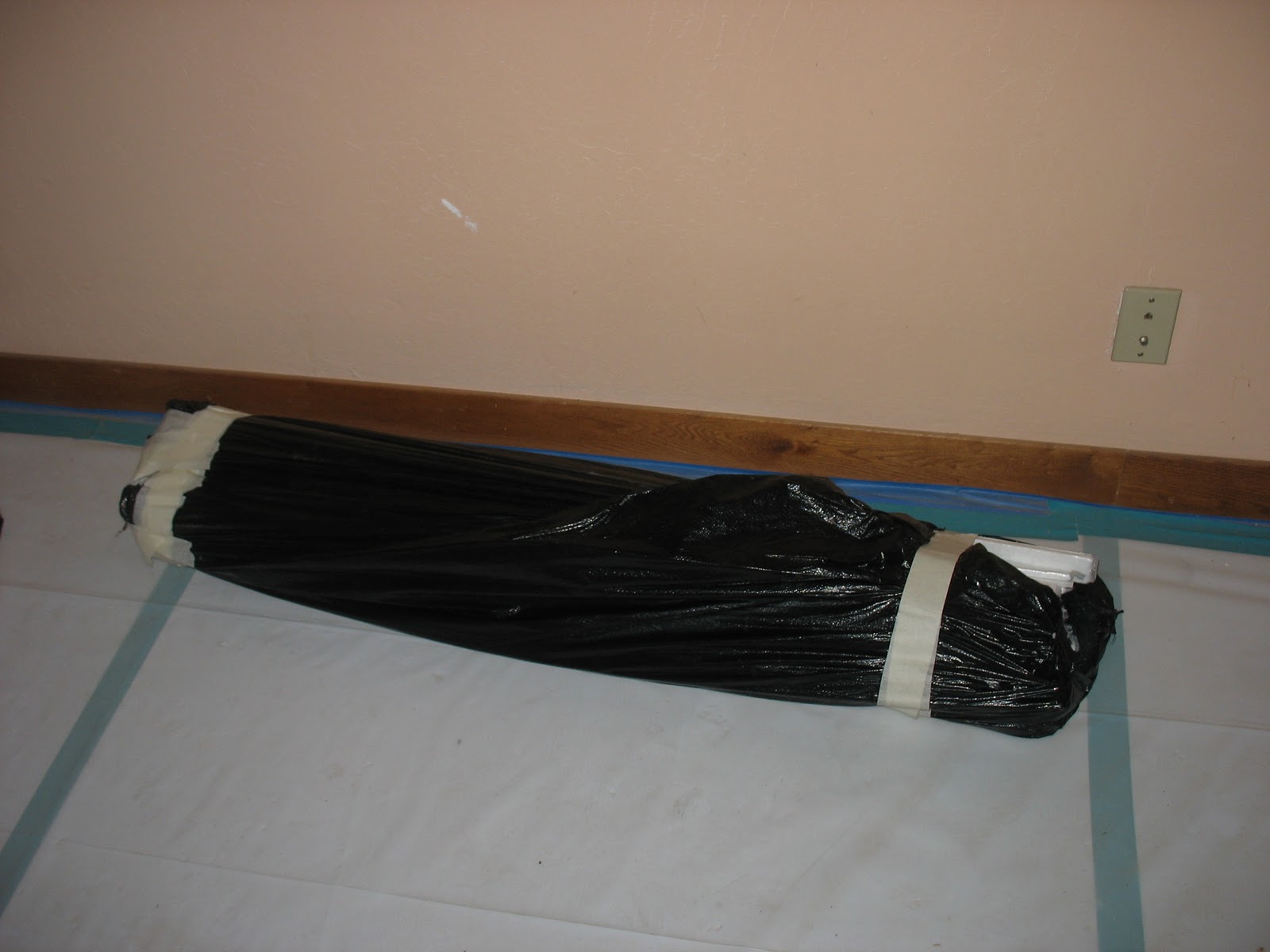
On Fri., a package arrived with the Thermablok. The guys at Acoustiblok (the company that sells Thermablok) like packaging. The entire thing was packed in heavy cardboard with duct tape on both ends. Inside that, the Thermablok strips were bundled together in plastic garbage bags that were also duct-taped:
 Inside these, the Thermablok strips themselves were packages in shrink-wrap:
 Here's a closer view of the label:
 I took the strip and set it against a stud to see how it would look when installed:
 Here is a closer view of the bottom:

The old drywall was not removed under the molding, so you can see how the Thermablok strip will line up with areas where there is still old drywall. Only about 0.1" of space separates the face of the old 0.5" thick drywall from the 0.39" thick (after the plastic strip is removed) Thermablok strip.
This is a problem. The thinnest drywall you can get is 0.25" and that is not recommended on framing with 16" centers The recommendation is for 0.5" thick drywall, probably because drywall has very little structural strength, and 0.25" therefore has much less strength that 0.5". So if 0.5" drywall is installed, the new drywall will stick up 0.4" beyond the existing drywall and various other stuff on the wall (electrical sockets, window sills, etc.). I looked around for alternative wall covering material that is thinner than drywall, but there doesn't appear to be much of anything. If we were planning on doing thermal bridging treatment for the whole house, this problem could cause a lot of additional work. All the molding would need to be taken off, maybe the electrical boxes would need to be moved, etc. But since we are only planning on doing one wall, the amount of work should be fairly limited.
I discussed thermal bridging in this previous post. The conclusion was that it would be too expensive and difficult to treat the whole house for thermal bridging, besides which, the insulation and drywall contractors probably wouldn't know what to do. However, I do want to treat the south wall of the hallway, to eliminate the condensation problem. So I ordered 50 strips of Thermablok , which I described in my previous post, enough to face the studs on the south hallway wall. Thermablok is an aerogel insulation that comes in 4' by 1.5" strips. The back of the strip has adhesive on it. Installing it couldn't be easier: you peel off the plastic strip and paste it onto the face of the stud (making sure of course there is no drywall dust or other dirt on the stud to clog up the adhesive). Aerogel is the most effective insulating material after vacuum, at around R-10/inch. These strips will add R-4 to the studs, effectively doubling the insulating value of a 2x4. But aerogel isn't cheap, the strips are about $4 apiece.
On Fri., a package arrived with the Thermablok. The guys at Acoustiblok (the company that sells Thermablok) like packaging. The entire thing was packed in heavy cardboard with duct tape on both ends. Inside that, the Thermablok strips were bundled together in plastic garbage bags that were also duct-taped:


The old drywall was not removed under the molding, so you can see how the Thermablok strip will line up with areas where there is still old drywall. Only about 0.1" of space separates the face of the old 0.5" thick drywall from the 0.39" thick (after the plastic strip is removed) Thermablok strip.
This is a problem. The thinnest drywall you can get is 0.25" and that is not recommended on framing with 16" centers The recommendation is for 0.5" thick drywall, probably because drywall has very little structural strength, and 0.25" therefore has much less strength that 0.5". So if 0.5" drywall is installed, the new drywall will stick up 0.4" beyond the existing drywall and various other stuff on the wall (electrical sockets, window sills, etc.). I looked around for alternative wall covering material that is thinner than drywall, but there doesn't appear to be much of anything. If we were planning on doing thermal bridging treatment for the whole house, this problem could cause a lot of additional work. All the molding would need to be taken off, maybe the electrical boxes would need to be moved, etc. But since we are only planning on doing one wall, the amount of work should be fairly limited.
Monday, December 20, 2010
Hydronic Radiant Heat Systems and Foam Insulation
Our radiant heat system is what hydronics contractors call a "staple up". We have a crawlspace and the house originally had forced air heating. Unlike houses with radiant installed from the start, where the heating pipes are threaded through a poured concrete floor or slab prior to pouring the concrete, the pipes in our case are fastened to the subfloor. The contractor who installed our radiant system crawled around under the house for 2 months threading pipe between the joist bays beneath the floor.
For insulation, he stapled polyethylene/foil bubble wrap radiant barrier insulation immediately under the pipes, with a small gap to allow the radiant barrier to function properly. Below that, he installed 4" of fiberglass batt. The house previously had fiberglass batt insulation under the floor, but, as I've mentioned before, fiberglass batt is a poor choice for insulation, and even worse in an application such as this. It has a tendency to sag, and in this case, because there is nothing across the bottoms of the floor joists, the tendency is even worse. In a wall-based application, at least the drywall is holding it in place, but I think the insulation contractor used fishing line or something to hold it up.
So as part of our quest to tightly seal the thermal envelope in our building, we decided to have closed cell foam blown into the spaces between the floor joists, just like in the walls and ceiling. But the situation is more complicated there, we can't simply foam on top of the pipes, since there needs to be some clearance. The foil radiant barrier provides that clearance, but will it withstand the pressure of the foam expansion? At first, Forrest, our architect, thought not, so we discussed installing some metal plates in place of the foil radiant barrier. But Paul said that would result in a much larger expense and delay. I asked Paul whether Ponzini, our insulation contractor, could do a test item that would determine whether installing the foam on top of the radiant barrier would work. Here's a picture of the test item:

The test item consists of two 2x8's with a plywood top simulating the floor assembly, and some radiant barrier stapled partway down. Below, you can see the radiant barrier and the gap:

The foil radiant barrier seems to hold up well, the foam pressure isn't enough to collapse it. So we are going forward with foaming on top of the radiant barrier. I have, however, asked Paul to check whether there is enough clearance on all the pipes and to ensure that the barrier is firmly stapled in place and hasn't collapsed in the 4 years since we had the hydronic system installed.
One issue that does concern me is leaks. A large earthquake could separate the PEX tubing from the manifolds and zone pumps. Leaks within the PEX tubing are less likely, but still possible if a pipe fails due to long term deterioration. With closed cell foam insulation, the water would accumulate between the insulation and subfloor, ultimately leaking out upwards and possibly warping the subfloor. The only indication of a leak is that the hydronic system starts drawing a lot of water out of the domestic water supply and the system pressure gauge indicates a drop in pressure from the normal 7 psi. But the pressure gauge is in the hydronic closet and we mostly don't look at it (though of course if there is a large earthquake we probably will check it to make sure the system is OK).
I briefly searched the Web for some water sensors that we could put into the floor to detect a leak directly. They all require replacing AA batteries at periodic intervals, a nonstarter since the sensors would be sealed into the floor by the insulation. This is a general problem with current sensor technology. If you want to put a sensor in an inaccessible place, even if it could have a wireless data connection, you still need to supply it with power through a wire. I called Kevin Smith, our hydronic contractor (he now has his own company, IntuitiveClimateControl) to discuss options and he said there are a variety of sensors we could put on the water line to the hydronic system that would measure and report if the hydronic system began to draw water at an accelerated rate. So when we finish the job, I'll probably look into putting in a sensor, but not now. There are too many things to finish up, and we just want to get this job done so we have our living space back.
Neither Paul nor the insulation contractor seemed to know much about our situation, which leads me to believe that they haven't run up against a hydronic stapleup that needs closed cell foam. I wonder if anyone else has tried closed cell foam insulation together with a staple-up hydronic system?
Sunday, December 19, 2010
Duke Comes Through (Sort of...)
A couple weeks ago, our good friend Duke came through and fixed the problems with the HRV venting... sort of. In the front, he cut a new vent, which is supposed to be for the HRV exhaust, below the attic vent. He hadn't switched the actual ducts yet, so the intake duct was connected to the new vent rather than the exhaust, but he knew about the problem and was planning on switching the ducts around when he came back to install the fitting on the condensate drain. Apparently, Fantech forgot to ship a condensate drain fitting along with the HRV unit. Duke ordered it, it was supposed to be here that Fri. Unfortunately, our good friend Duke is lacking in, shall we say, aesthetic sense. The concept of "curb appeal" is lost on him. Consequently, the front of our house now looks like this:
 The new duct is about 3 inches lower than the old one, instead of nicely aligned. Rather than try to fix the problem, which would involve filling in the hole, we're simply going to paint the ducts the same color as the house and leave it at that. They should blend in enough with the house that they won't be all that visible. We also needed an electrical outlet to plug the front HRV in, but that's the electrician's job. He was supposed to install it that week.
Speaking of aesthetic issues, the HVRs require piping to drain off any condensate that might occur on the heat exchanger. The missing fitting is what was holding up the front HRV. Since the HRVs are installed in attic areas without any plumbing, there needs to be some way to get the water out of the HRV and drained away. Here's what our back condensate piping looks like:
 The white pipe coming out through the wall is the condensate drain. You can also see the solar panel for one of our solar garden pumps near the top. This white pipe doesn't look so nice either, and will ultimately be painted. The pipe is unfortunately PVC. PVC is not a particularly environmentally friendly material. I asked Paul why they couldn't use ABS pipe instead, but ABS doesn't come in the 1/4" diameter stock that is needed for this application.
On the back, we now have a veritable proliferation of hoods:
 Only the one on the lower right and upper left will ultimately stay. The others will disappear when the siding is replaced in the triangle on the right side of the picture. Then they will recut the vent on the lower right, which will be an attic vent. The upper left vent is the HRV intake. The HRV exhaust has moved to the roof:
 It should be the tall one, the small one is the bathroom (high speed) exhaust. Below you can see how Duke rerouted the bathroom exhaust duct out the roof:
 It is the hard, elbow-shaped pipe running up the middle of the picture. The exhaust is the soft duct on the upper left.
As they came from Fantech, the SH704s have no low voltage switch. You just plug them in and they start up. I'm not sure what Fantech had in mind as far as control. A Web search turned up the Aubetech 1702-3W which is a three wire, high voltage (i.e. 110V), 7 day timer switch with maximum 2 settings per day. I ordered and received 2 Aubetechs for the HRVs. They are rated for up to 1 HP motors, the Fantech motors are less so there should be no problem. This will allow the HRVs to turn off during the day when we are at work, and on again in the afternoon. The electrician needs to wire them up yet. We are going to put them into the closets in the bedrooms nearest the HRV units, so they are not visible from the room.
I also started the HRV above the master bedroom and, to my surprise, there was no problem with vibration at all. While the actual HRV unit itself vibrated due to the fan motor, the vibrations were not transmitted through the shock absorbers to the house frame. There was a very faint noise in the downstairs bedroom, about what we hear when the solar thermal pump goes on, which I assume was from vibrations transmitted through the air to the ceiling. With closed cell foam in the ceiling and additional soundproofing, I think the noise level should be OK.
This week, Paul, Christine, and I checked the HRVs and it seems like everything has been properly installed. The ducts are routed out the right vents, the front HRV has an outlet, and the condensate drain is in on the front HRV. The electrician still needs to install the Aubetechs yet, but he's started the wiring. All in all, it looks like our adventure with HRV installation is slowly drawing to a successful, if not entirely satisfactory (from an aesthetic standpoint) close. In a future post, I'll give a retrospective.

Speaking of aesthetic issues, the HVRs require piping to drain off any condensate that might occur on the heat exchanger. The missing fitting is what was holding up the front HRV. Since the HRVs are installed in attic areas without any plumbing, there needs to be some way to get the water out of the HRV and drained away. Here's what our back condensate piping looks like:

On the back, we now have a veritable proliferation of hoods:


As they came from Fantech, the SH704s have no low voltage switch. You just plug them in and they start up. I'm not sure what Fantech had in mind as far as control. A Web search turned up the Aubetech 1702-3W which is a three wire, high voltage (i.e. 110V), 7 day timer switch with maximum 2 settings per day. I ordered and received 2 Aubetechs for the HRVs. They are rated for up to 1 HP motors, the Fantech motors are less so there should be no problem. This will allow the HRVs to turn off during the day when we are at work, and on again in the afternoon. The electrician needs to wire them up yet. We are going to put them into the closets in the bedrooms nearest the HRV units, so they are not visible from the room.
I also started the HRV above the master bedroom and, to my surprise, there was no problem with vibration at all. While the actual HRV unit itself vibrated due to the fan motor, the vibrations were not transmitted through the shock absorbers to the house frame. There was a very faint noise in the downstairs bedroom, about what we hear when the solar thermal pump goes on, which I assume was from vibrations transmitted through the air to the ceiling. With closed cell foam in the ceiling and additional soundproofing, I think the noise level should be OK.
This week, Paul, Christine, and I checked the HRVs and it seems like everything has been properly installed. The ducts are routed out the right vents, the front HRV has an outlet, and the condensate drain is in on the front HRV. The electrician still needs to install the Aubetechs yet, but he's started the wiring. All in all, it looks like our adventure with HRV installation is slowly drawing to a successful, if not entirely satisfactory (from an aesthetic standpoint) close. In a future post, I'll give a retrospective.
Wednesday, December 15, 2010
The Last of the Drywall Removal
We are hopefully finally, finally done with drywall removal. Due to a screwup by The Project Manager Who Shall Not Be Named, the original drywall removal effort failed to remove drywall from 4 different areas on the thermal envelope. Two of those were small enough that they could be removed without calling the drywall removal contractor back, but the other two were not. One was fairly obvious, it was the back wall of the southeast upstairs bedroom (Bedroom3), and we called the drywall removal contractor back to do that in September. But the last area was a 4' wide section on the southeast wall of the main hallway that Christine caught when she was in the house a couple weeks ago. We had it removed this week:

Our house has lots of small wall runs along the thermal envelope like this one. While they give the house a kind of quirky aesthetic (actually, one reason why the house appealed to us in the first place), they do increase the surface area for heat leakage and complicate insulation. If the house were just one big, four walled box sealing it would be simple but it would be less interesting from an architectural standpoint. Proper air sealing becomes even more important for these small runs, and especially the joints between the short runs and the rest of the wall. You can be sure I will be looking for that when I do the inspection after the insulation contractor is finished.

Our house has lots of small wall runs along the thermal envelope like this one. While they give the house a kind of quirky aesthetic (actually, one reason why the house appealed to us in the first place), they do increase the surface area for heat leakage and complicate insulation. If the house were just one big, four walled box sealing it would be simple but it would be less interesting from an architectural standpoint. Proper air sealing becomes even more important for these small runs, and especially the joints between the short runs and the rest of the wall. You can be sure I will be looking for that when I do the inspection after the insulation contractor is finished.
Saturday, December 11, 2010
PG&E and Electric Car Chargers
If you recall, we applied to PG&E for a 200 amp service upgrade at the beginning of November (we currently have 100 amps). The request has been grinding its way through PG&E's process. A few weeks ago, we informed them that we would be getting an electric car next year. This week, The Lovely Wife got a call from a Glenn, from PG&E. He asked to speak with me. Because he called TLW on her cellphone, I wasn't there. But he never called me back. On Thurs. at our weekly project meeting, Paul told me that he had spoken with Glenn (I guess he thought Paul was me) and what PG&E wanted. What they wanted was to know whether we wanted a second meter for the electric car.
I was puzzled. Why would we want a second meter? Paul said that PG&E wanted us to charge the car at night, to avoid overloading their transformer and the circuits that supply our neighborhood. The claim is that an electric car establishes a load equivalent to another house. The charger draws maximum 40 amps at 240V (but most likely less than that, since breakers are typically overprovisioned). That's 4.8 kw, a pretty hefty sum, and that over 6 hours, for a total of 28.8 kwh. If I'm the only person in the neighborhood charging, then there is probably no problem. But if electric cars catch on, PG&E is in trouble. They will quickly run out of overprovisioned capacity and need to start upgrading their transformers and other "last mile" circuits. As we know from the telcom world, utilities hate to upgrade "last mile" infrastructure because there is a lot of it and therefore upgrading is expensive.
I don't think PG&E has much to worry about, personally. I suspect my neighbors with houses built in the 70's like mine (some were built later) all have a 100 amp mains feed like ours does. In our neighborhood, the mains feeds are underground rather than coming from a pole, which makes the neighborhood look nicer but makes upgrading a real challenge. Rather than simply restringing a wire, PG&E needs to bring in a backhoe, dig up the conduit, and replace the 100 amp line with one that will handle 200 amps. Backhoe work is expensive and PG&E's process is time consuming. I can't see any of my neighbors going through that kind of grief, unless gas gets up to $6.00 a gallon. Then maybe even the two neighbors across the street with two SUVs each might have second throughts.
Anyway, I pondered briefly if we did want a second meter for the electric car charger. PG&E offers a special tariff for electric car charging service, called E-9. The cost works out to around $0.06/kwh at night and $0.30/kwh during the day. So there is a real financial incentive not to charge during the day when more power is being used by businesses and residences. But we are already on a time of use tariff, E-7W, for our solar PV. This has the same kind of incentive: $0.09/kwh at night most of the year and $0.30/kwh during the afternoon in summer (the winter rates are much less). The rate on summer afternoons is high because PG&E needs the power for all the air conditioners in the Central Valley. We can save big time by not using power then and banking the credits for the winter, when our solar panels get little sun and the folks in the Central Valley have their gas heaters cranked up instead of their air conditioners.
But the $0.03/kwh differential in price caused me to haul out my calculator. Would we save by taking a second meter an the E-9 rate? Our new solar PV system has 2000 kwh/year capacity designed in for the Nissan Leaf. This amounts to around 8000 mi/yr, the amount we usually drive our around town car, at 0.25 kwh/mi, the amount of energy a reasonably aerodynamically efficient electric car uses. Since we cannot connect up the solar PV system to more than one meter, the generated power would not offset the power we use for the electric car on the second meter. Instead, PG&E would reimburse us for it, which they will start doing next year. The rate we get is paltry, $0.08/kwh, even for the expensive power we generate in summer (this is a ripoff in my opinion, but that's the subject of another post).
We would end up paying $120/yr for power on the E-9 rate and getting back $160/yr for the solar power we sell to PG&E on the main meter, for a grand total of $40 to our credit, enough for a nice lunch for two at a fancy Palo Alto restaurant. Looks good, right? Think again! PG&E also charges you $75/yr for renting the meter. So we would end up paying $35 more with a second meter than with a single meter. And, in addition, we would be constrained to always having to charge at night, even if we occasionally need to charge in the afternoon on a weekend because we have taken the car somewhere (this happens sometimes with our current plug-in hybrid). So our answer to PG&E is a polite: "Thanks but no thanks."
According to PG&E's online schedule, the 200 amp upgrade begins Dec. 24. Think of that: PG&E as Santa Claus!
Friday, December 10, 2010
More on MPP Balancing v.s. Microinverters
IEEE Spectrum has a short article this month discussing MPP balancers v.s. microinverters for optimizing power from solar PV systems. If you recall, in this post, I discussed the reasoning behind my decision to go with Tigo's MPP balancer solution v.s. a microinverter solution such as Enphase. Suprisingly (at least to me) the author of the article confirmed the reasoning. The author found the MPP balancers, in particular Tigo, better than microinverters because the electronics are simpler and cheaper and there are no electrolytic capacitors to fail. The complicated part is not up on the roof, it is down next to the inverter doing calculations, so it is much easier to replace. REC Solar (the company we are having install our system) tried out both microinverters and MPP balancers at its corporate headquarters for a year before going with Tigo, something we in Silicon Valley call "eating your own dog food."
The REC sales guy also mentioned something about an infrared picture of a system with a microinverter where the microinverter was in the center of a huge red area of high temperature. I searched a bit but couldn't find it. I found a forum where there was some discussion of microinverters v.s. MPP balancers. The claim from the microinverter faction is that microinverters are mounted on the panel racking and therefore don't touch the panels, but even so, they increase the temperature by around 6F. That shouldn't be enough to cause major problems if properly installed, but a slight bit off and the panel could get cooked. Temperature increase was another one of my concerns. It can cause premature panel aging and will in any case reduce the amount of power produced by the panel. MPP balancers use DC-DC conversion to maintain the voltage at an optimal level for maximum power output. This results in less heat loss near the panel, though, of course, the centralized inverter still is not 100% efficient so the inverter can heat up. But it is easier to put the inverter in a shaded area, or an area with some wind to dissipate the heat.
Really, the only advantage I can see of microinverters is that they can be installed by someone with essentially no training, except in standard AC wiring. MPP balancers require training to install. This of course makes the labor cheaper, but - the professionalism of American construction technicians being in general what it is - you get what you pay for. If the guy installing it decides, hey, why not just clip the microinverter to the panel nobody will notice, it will end up prematurely aging the panel. Then they get to come back and replace it, for a fee. We've had plenty of experience on this job with that kind of reasoning.
I also discovered I need a CAT5 cable from the monitoring box to where my DSL router is located (technically it is a DSL modem cabled to a Linksys router, I have an older model modem). Luckily, the walls are completely open, since the electrician will need to run the cable through the walls from the front of the garage to around the middle of the house on the second floor, where our home office is and where we keep the DSL modem. I asked Tigo about a WiFi wireless bridge. These devices are not access points, but act like a wire without the copper. Tigo discouraged me from using one. They claimed that the wireless bridges often go down and then they need to call up the homeowner and ask them to reboot it. The Tigo box sends measurements to the Internet every 10 minutes, and can buffer up to 2 days worth of data. Tigo monitors the condition of the panels and I guess lets the homeowner know if there is some problem.
I think the assumption behind the wireless bridge manufacturers is that they will be used in an office setting and therefore someone will notice if they go down because YouTube isn't coming up. Then somebody will reboot the bridge. For machine to machine communications, though, the reliability must be much higher, otherwise, you end up with an expensive "truck roll equivalent" in which some person must find the box (could be difficult if it is in an out of the way place) and reboot it. Perhaps wireless links are better for control systems, where a person is dialing temperature up or down or setting a timer on a fan. In that case, if the wireless link is faulty, it should show up on the remote and the person operating it can take some action, like replace the batteries in the remote.
So we'll go with the CAT5 cable, and, in addition, get another from the solar hot water tank so that we can at some point put Internet data recording for that too. With data on both, I can get a much better picture of how much of the house's energy is coming from our renewable energy systems.
Sunday, December 5, 2010
More on Optimal Solar Thermal Backup
If you recall, in this post, I discussed why we chose an electric on-demand hot water heater for backup to our solar thermal hot water system. The conclusion was that electric on-demand was best because:
On the downside, electric on-demand units draw an enormous amount of current. Our unit has 3 220V/20 amp heating units. When all units are active, it will draw more current than the hot tub does. The utilities don't like that kind of draw because it causes transformers to heat up, and can cause lights to flicker in the house, especially if there is more than one on-demand heater active in a neighborhood at a time. You need to have a 200 amp residential service in order to install one, we have a 200 amp service upgrade on order from PG&E.
But the utilities are going to have to upgrade their transformers and circuits for electric cars anyway. Gas on-demand units also require a large (1" I think) gas main, which many residences don't have, so even with gas-on demand you may need a residential service upgrade from the utility. And, for solar backup, the on-demand heater must only heat the water from 80F to 120F, not from 60F which is the usual water main temperature here in winter (our solar hot water tank is now around 80F due to cloudy weather), so it is less likely that, in our case, all three heating units will fire at once. All things considered, electric on-demand seems to be a better option for solar thermal backup.
- On-demand allows the solar hot water to contribute the maximum amount of energy. If you have a tank-based backup, either integrated with the solar hot water tank or in a separate tank, the backup energy source will come on whenever the tank goes below 120F and will heat the whole tank, whereas the on-demand heater only comes on to heat the water you need.
- Electric on-demand is better than gas on-demand because the electricity can be directly offset by installing more solar PV. But even if you don't consider the offset, electricity is better because the electric grid is incorporating fossil carbon-free energy sources faster than the gas grid.
- Gas on-demand requires complex venting whereas electric on-demand is just another appliance you can fasten to the wall in a closet (which is what we are doing).
On the downside, electric on-demand units draw an enormous amount of current. Our unit has 3 220V/20 amp heating units. When all units are active, it will draw more current than the hot tub does. The utilities don't like that kind of draw because it causes transformers to heat up, and can cause lights to flicker in the house, especially if there is more than one on-demand heater active in a neighborhood at a time. You need to have a 200 amp residential service in order to install one, we have a 200 amp service upgrade on order from PG&E.
But the utilities are going to have to upgrade their transformers and circuits for electric cars anyway. Gas on-demand units also require a large (1" I think) gas main, which many residences don't have, so even with gas-on demand you may need a residential service upgrade from the utility. And, for solar backup, the on-demand heater must only heat the water from 80F to 120F, not from 60F which is the usual water main temperature here in winter (our solar hot water tank is now around 80F due to cloudy weather), so it is less likely that, in our case, all three heating units will fire at once. All things considered, electric on-demand seems to be a better option for solar thermal backup.
Sunday, November 28, 2010
HRV Problems
The HRV system was finally "completely" installed, by Duke's HVAC. Here's what I discovered on the back of the house one day a couple weeks ago when I got home from work:

The upper hood in the middle is the existing high speed bathroom ventilation. The ones on the lower left and right were meant to be the HRV intake and exhaust. Fantek customer support recommends that, on the same plane, the intake and exhaust vents should be at least 6 feet apart, and that the intake should be at least 6 feet from any other exhaust including attic vents. The maximum distance in this case is 3 feet between the bottom two vents, and 1.5 feet between the bottom two and the middle one.
When I complained to Paul, he asked where I wanted them. I considered what would be the easiest thing to do. There's very little room on the wall in the chase upstairs. The diagonal distance between the lower right hood on the picture and the upper left corner where the wall runs is maybe 5 1/2 feet. So I said why not put the intake on the roof, thinking perhaps it would have a longer pipe like a chimney.
Here is what we got:

The intake is so short it will draw in fumes from the asphalt shingles when they heat up.
I remeasured everything this morning but there is simply no way we can get 6 feet between the HRV exhaust, bathroom exhaust, an attic vent, and the HRV intake. It seems fairly clear that the bathroom exhaust needs to go out the roof vent, since it will be fairly strong. I also think the HRV exhaust will need to go through the roof, since I don't see any place where we can put it on the wall. The attic vent can stay on the right lower side of the back house wall in the picture above. That leaves the HRV intake. We could run a duct into the bedroom and out the bedroom wall, extending the chase we put in for the duct that runs to the hall. The extension would be below the wooden frame in this photo:

The vent would then run out the wall on the right side. Or we could simply put the duct at the upper corner of the attic area even though it is around 6" short. That might not be such a problem, since the attic vent won't be forcing air out like the exhaust. The hood will direct it downward and the intake will be much higher on the wall.
The front HRV is in better condition. There, I asked our good friend Duke to direct the intake through an existing attic vent in order to reduce the number of vents on the front of the house, but Fantek customer support tells me there needs to be a separate 6" hooded vent for the pressure to work. So we can just move the exhaust to the bottom below the attic vent, and put the intake where the exhaust is now. That way, the exhaust will not re-enter the house through the attic vent, and there is at least 8' between these vents and the intake.
One thing is for certain, though. You would have thought our good friend Duke would have given Fantek technical support a call before he started hacking around on the back side of our house. I'm certain at least one and possibly two of the holes need to be patched, either in place or by replacing the siding and cutting new holes.
The other problem is that I have an ominous feeling about the noise the HRV will generate. On Monday, I was working at home and several times a rumbling noise started up above my head. I think this was probably our good friend Duke starting up the HRV unit. I tried it again today and it was nowhere near as quiet as the unit Paul showed us at another job he did, when we were trying to decide if we wanted to put in HRV. Paul showed us an HRV installation he had done himself, in which the unit was hung from wires. No vibrations are transferred to the building structure. Running fully on, the HRV was absolutely quiet, and we requested that our unit be mounted similarly. But when I got home from a conference in Washington earlier this month, I found that our good friend Duke had used heavy metal bars to fasten this one down, though there were a couple of shock absorbers and some missing rubber gaskets which supposedly would cut down on the vibrations. He installed the rubber gaskets on Monday but if what I heard on Monday was the HRV, there still might be vibrations transferred to the house frame.
Wednesday, November 24, 2010
Thermal Bridging
I've done some research on limiting thermal bridging. 25-27% of the interior surface in a typical stick-built building in the US consists of the face of the studs, headers, and other structural elements that extend through the walls from the inside to the outside. Our exterior sheathing is really simple due to the fact that the house was build in the 1970's before people understood about these things: one layer of plywood on the outside and tarpaper on the inside of the plywood to reduce moisture contact from rain and condensation. So the studs extend between the exterior sheathing and the interior drywall, acting as a major thermal bridge. Thermal bridging reduces the R-value of the walls by a considerable amount. A 2x4 stud is around R-4 while a 2x6 is around R-6. Even if the cavities between the studs are insulated with R-6/inch closed cell foam (for a cavity R-value of R-21 for a 2x4 wall or R-33 for a 2x6 wall), the impact on the wall assembly is a reduction in R-value of around 33%. For example, an R-19 insulated wall is reduced to R-12.8 by thermal bridging. Condensation on the interior surface of the studs and mold growth is a possibility. In fact, we found some minor mold growth on the interior studs of the back hallway wall. This wall gets no sun in winter at all, so it is possible that some condensation occurred during an especially cold winter night and never dried out the next day.
Thermal bridging is most evident in thermal imaging pictures. Consider this image taken of the master bedroom wall (unfortunately not being re-insulated at this time since we are living in it):

If you are interested in major problems, the bright blue along the corners where the walls and ceiling meet obviously draws the eye. These are places where the fiberglass batt insulation was improperly installed or has sagged with age (it is the former in this case, we had this room remodeled only 4 years ago). Major thermal leaks are occurring. But the thermal bridging effects of the studs can be seen in the dirty blue lines extending downward from the ceiling. These are the thermal traces of the studs. Reinsulating the wall with closed cell foam will get rid of the bright blue along the corners, but not the dirty blue below.
One very nice solution to thermal bridging is a product called Thermablok. The product is 4'x1.5"x0.4" strips of aerogel. The strips have a sticky side like tape, and are designed so that the backing can be removed and the strips simply stuck to the face of the studs. Aerogel is the best insulating material known, R-10 per inch, short of full vacuum. The R-value for a Thermablok strip is around R-4, effectively doubling the insulating power of a 2x4 stud. The cost is $1/linear foot or $4/strip, on the expensive side compared to materials like fiberglass batt or even spray foam.
I looked into Thermablok as a possible solution to thermal bridging in our house. A couple years ago, I made a thermal model of our house which required measuring all the walls. It is not perfectly accurate, but I think it gives a good estimate. The estimate of the area for the currently removed thermal envelope is 2520 sq. ft. At 25% stud area, the amount of stud area is 630 sq. ft. This would require 1261 4'x1.5" Thermablok strips, which, at $1/linear foot would be $5041, in addition to the labor to install it. And this price does not include the studs under the floor. This is pretty expensive. Besides that, as Paul mentioned when I brought up the topic in one of our meetings, rigid spray foam is rarely flush with the face of the studs, so there would be additional bridging through the rims of the studs that are exposed above the foam.
In an effort to find a cheaper solution, I googled around a bit for some more information. I found this reference which describes how to handle thermal bridging with normal insulating materials. Ideally, the external walls should be sheathed with extruded polystyrene board on the outside, but of course we can't do that. The recommendations that we could follow are:
The reference above doesn't mention under the floor, but I think we get thermal bridging through the floor too. So the same treatment as for the ceilings would probably be appropriate though it might be possible to use thinner strips to hold the rigid board in place and a 1"polyiso would be sufficient, since the crawlspace is already pretty tight and heat loss downwards isn't as serious as heat loss upwards.
I think the HRV chase upstairs would need a different treatment, because there simply isn't any space to get polyiso board in, besides which, it might crack and come loose when trying to crawl back into the space, for example, to service the HRV unit. I think that area could be done with Thermablok since it is relatively small. The area is around 38 sq. ft. and it would be about $76 for Thermablok. So I think it should be possible to install the Thermablok by hand and use some touch-up foam along the studs where the spray foam didn't cover to the top of the stud.
We also opened up an area from the outside under the living room window where we could do exterior sheathing. There is a large, exposed footer that will act as a major thermal bridge. I don't know if enough clearance exists for 1" rigid board, though, since the window assembly is already in place. Thermablok could probably be used in this area, since the amount would be relatively small. Since Thermablok is only 0.4" think, there should be less problem with clearance.
Unfortunately, we can't do anything about the footers and headers from the outside in the rest of the house because the siding is in place. We can mitigate bridging through the headers from the inside somewhat by ensuring the rigid board is sealed along the headers, and that gaps are filled with touchup foam, but we can't do anything about the footers because the floor is in place. We also can't do the wall between the garage/attic and hallway/kitchen because we had that redone several years ago and I was primarily interested at that point in simply reducing air infiltration to improve air quality, and not in reducing heat loss to the maximum extent possible.
Eliminating thermal bridging is one of the treatments necessary to build according to the German Passivhaus standard. The Passivhaus standard aims to get away with really minimal additional active heating and cooling, and uses HRV quite extensively. We are never going to turn our house into a Passivhaus, but I thought we could learn from what they do and try to get our carbon footprint down even further. So it was with visions of reducing our carbon footprint from heating by 50% instead of 30% dancing in my head that I emailed Paul with the above suggestions for eliminating thermal bridging in our job.
Unfortunately, The Lovely Wife brought those visions crashing down. Already annoyed by the length of time the job is taking and my tendency to want to make things right, she pointed out that the insulation contractors who Paul was soliciting for bids had probably never done thermal bridging elimination before. And the drywall contractors probably hadn't dealt with trying to fasten drywall when the walls were sheathed in polystyrene board. Considering the fact that our HRV contractor screwed up some fairly simple aspects of the installation which he could have had right by calling the manufacturer's technical support (see forthcoming post), the probability that the insulation contractor and drywall contractor would completely screw up any thermal bridging treatment was very high. In addition, all the electrical outlets are already in place, so if we put in 1" polystyrene sheathing, they would need to either be moved outward or extended somehow, to say nothing of the places were the drywall was not removed.
Sadly, I sent another email to Paul and told him to forget about the thermal bridging treatment, except on the back wall of the hallway. The mold indicates a major problem, so we'll confine the treatment to just that wall. Because it is such a limited space, Thermablok to cover it should not be so expensive, and any areas where the spray in foam failed to cover the stud can be touched up by hand with can foam.
Thermal bridging is most evident in thermal imaging pictures. Consider this image taken of the master bedroom wall (unfortunately not being re-insulated at this time since we are living in it):

If you are interested in major problems, the bright blue along the corners where the walls and ceiling meet obviously draws the eye. These are places where the fiberglass batt insulation was improperly installed or has sagged with age (it is the former in this case, we had this room remodeled only 4 years ago). Major thermal leaks are occurring. But the thermal bridging effects of the studs can be seen in the dirty blue lines extending downward from the ceiling. These are the thermal traces of the studs. Reinsulating the wall with closed cell foam will get rid of the bright blue along the corners, but not the dirty blue below.
One very nice solution to thermal bridging is a product called Thermablok. The product is 4'x1.5"x0.4" strips of aerogel. The strips have a sticky side like tape, and are designed so that the backing can be removed and the strips simply stuck to the face of the studs. Aerogel is the best insulating material known, R-10 per inch, short of full vacuum. The R-value for a Thermablok strip is around R-4, effectively doubling the insulating power of a 2x4 stud. The cost is $1/linear foot or $4/strip, on the expensive side compared to materials like fiberglass batt or even spray foam.
I looked into Thermablok as a possible solution to thermal bridging in our house. A couple years ago, I made a thermal model of our house which required measuring all the walls. It is not perfectly accurate, but I think it gives a good estimate. The estimate of the area for the currently removed thermal envelope is 2520 sq. ft. At 25% stud area, the amount of stud area is 630 sq. ft. This would require 1261 4'x1.5" Thermablok strips, which, at $1/linear foot would be $5041, in addition to the labor to install it. And this price does not include the studs under the floor. This is pretty expensive. Besides that, as Paul mentioned when I brought up the topic in one of our meetings, rigid spray foam is rarely flush with the face of the studs, so there would be additional bridging through the rims of the studs that are exposed above the foam.
In an effort to find a cheaper solution, I googled around a bit for some more information. I found this reference which describes how to handle thermal bridging with normal insulating materials. Ideally, the external walls should be sheathed with extruded polystyrene board on the outside, but of course we can't do that. The recommendations that we could follow are:
- On the ceilings, 2" foil-faced rigid polyisocyanate board as sheathing on the inside held in place with 1x4 furring strips, 16" on centers
- On walls if you can't use exterior sheathing , 1" polystyrene board (XPS) held in place with 1x4 furring strips, but I think maybe polyisocyanate could be used there too since I think it is a greener material than polystyrene and has a slightly higher R-value.
The reference above doesn't mention under the floor, but I think we get thermal bridging through the floor too. So the same treatment as for the ceilings would probably be appropriate though it might be possible to use thinner strips to hold the rigid board in place and a 1"polyiso would be sufficient, since the crawlspace is already pretty tight and heat loss downwards isn't as serious as heat loss upwards.
I think the HRV chase upstairs would need a different treatment, because there simply isn't any space to get polyiso board in, besides which, it might crack and come loose when trying to crawl back into the space, for example, to service the HRV unit. I think that area could be done with Thermablok since it is relatively small. The area is around 38 sq. ft. and it would be about $76 for Thermablok. So I think it should be possible to install the Thermablok by hand and use some touch-up foam along the studs where the spray foam didn't cover to the top of the stud.
We also opened up an area from the outside under the living room window where we could do exterior sheathing. There is a large, exposed footer that will act as a major thermal bridge. I don't know if enough clearance exists for 1" rigid board, though, since the window assembly is already in place. Thermablok could probably be used in this area, since the amount would be relatively small. Since Thermablok is only 0.4" think, there should be less problem with clearance.
Unfortunately, we can't do anything about the footers and headers from the outside in the rest of the house because the siding is in place. We can mitigate bridging through the headers from the inside somewhat by ensuring the rigid board is sealed along the headers, and that gaps are filled with touchup foam, but we can't do anything about the footers because the floor is in place. We also can't do the wall between the garage/attic and hallway/kitchen because we had that redone several years ago and I was primarily interested at that point in simply reducing air infiltration to improve air quality, and not in reducing heat loss to the maximum extent possible.
Eliminating thermal bridging is one of the treatments necessary to build according to the German Passivhaus standard. The Passivhaus standard aims to get away with really minimal additional active heating and cooling, and uses HRV quite extensively. We are never going to turn our house into a Passivhaus, but I thought we could learn from what they do and try to get our carbon footprint down even further. So it was with visions of reducing our carbon footprint from heating by 50% instead of 30% dancing in my head that I emailed Paul with the above suggestions for eliminating thermal bridging in our job.
Unfortunately, The Lovely Wife brought those visions crashing down. Already annoyed by the length of time the job is taking and my tendency to want to make things right, she pointed out that the insulation contractors who Paul was soliciting for bids had probably never done thermal bridging elimination before. And the drywall contractors probably hadn't dealt with trying to fasten drywall when the walls were sheathed in polystyrene board. Considering the fact that our HRV contractor screwed up some fairly simple aspects of the installation which he could have had right by calling the manufacturer's technical support (see forthcoming post), the probability that the insulation contractor and drywall contractor would completely screw up any thermal bridging treatment was very high. In addition, all the electrical outlets are already in place, so if we put in 1" polystyrene sheathing, they would need to either be moved outward or extended somehow, to say nothing of the places were the drywall was not removed.
Sadly, I sent another email to Paul and told him to forget about the thermal bridging treatment, except on the back wall of the hallway. The mold indicates a major problem, so we'll confine the treatment to just that wall. Because it is such a limited space, Thermablok to cover it should not be so expensive, and any areas where the spray in foam failed to cover the stud can be touched up by hand with can foam.
Saturday, November 20, 2010
Solar PV Design
The process of finalizing a design and a contract with a solar installer took an incredible three months. We've decided to go with REC Solar since their preliminary bid came the closest to what we wanted. We started the process in early August when I sent a rough description of the system to Forrest, our architect, and The Project Manager Who Shall Not Be Named. TPMWSNBN subsequently quit (or was gently fired, not sure which), but he hadn't done anything to start the process rolling anyway. Around the end of August, Christine put out the contract for bids. I had thought that TPMWSNBN had conveyed to her what I wanted but, after the bids came back, we realized that was not the case. As previously reported, one bid came from a roofer "wanting to get into solar installation" (we declined to pay for his training), one came from a nonprofit that sends volunteers up on your roof to install the system (our roof is quite steep and a professional roofer fell off when we had it replace in 2003, broke his collarbone, and required 3 operations), and a professional solar installer. Not surprisingly, the professional solar installer came closest to what we wanted, but it was not quite right. So we started the process over again sometime around the end of Sept.
One of the problems we have is that our job is not the typical situation that most solar installers face. Most people who get solar don't have any in the first place, and so the solar installer can take a year's worth of PG&E electrical usage data and come up with a good estimate about how the homeowner can eliminate 80% of their PG&E bill by installing solar. At which point, the homeowner is thrilled because the estimate shows them paying PG&E far less. In our case, we already have a solar PV system, so our bill tells the installer little about our electrical use. We still draw about 2000 kwh from the gird, but we pay nothing for that power because PG&E credits us around 3x for power generated on summer afternoons what we pay for power at night, when we are recharging our converted plug-in Prius, and in the winter, when we have lots of lights on and the furnace runs. We never use up the surplus credit, though we have been coming closer since we converted our 2008 Prius to a plug-in hybrid. We also are also primarily interested in completely offsetting the carbon footprint from our electricity usage, not in eliminating or reducing our electric bill, though of course that should follow if we completely offset the electricity usage.
In addition, we are having some new electric appliances installed, and are planning on buying a Nissan Leaf electric car next year. So we need somehow to plan a system that will offset our current grid draw and, in addition, offset the usage from the new appliances and the electric car if we want to eliminate our carbon footprint. Estimating the usage from the appliances is straightforward, but with the car, the electrical usage is likely to be somewhat more unpredictable. However, I came up with the following projected usage requiring offset in addition to the power provided by our current 2.5 kw system:
My original plan was to add a 30% margin to that to allow for power usage growth in the future. For example, if we revisit the decision not to install a geothermal heat pump, or even maybe go for an air source heat pump, we would then remain carbon neutral without having to install new panels. However, I found out near the end of the design process that PG&E won't allow solar installers to put in more panels than will completely offset the homeowner's electricity use, without good reason. Theoretically, this would not have allowed us to offset the new appliances or the Nissan Leaf because they weren't on our bill last year. REC and the other companies bidding on the contract kept sending bids for 18 panels, or 26 panels, until finally the REC engineer explained the problem. When I told them about our situation, the REC engineer accepted my explanation - that we were buying an electric car - as sufficient justification for a larger system. However, they would not let me include a 30% margin. This is unfortunate, because I was planning to offset the carbon generated by our gas hydronic furnace, gas stove, and new gas fireplace from the portion of the 30% margin that we didn't use. I guess we will just have to continue to buy carbon credits for that, as we are doing right now.
I also originally requested Sunpower E19 modules which generate 315 watts/panel, thinking that more watts per panel would reduce the number of panels and therefore the amount of space on my roof taken up by the PV system. However, Christine pointed out that the E19 was actually larger than standard modules, around 10" wider, though the same length. So, in effect, we would end up using about the same amount of roof space with the E19 as with a set of standard panels that generate 235 watts/panel, the maximum currently available in a standard-sized residential panel. REC also advised not to go with Sunpower, since they are a name brand and they charge extra for the brand. They instead recommended the Kyocera 235 watt module, the KD235GX-LFB. This model produces exactly the same amount of power as the Sunpower E18 series (which is standard sized) but is cheaper.
My original calculations, including the 30% margin, came up with a total system size of 6.85 kw DC. However, I failed to account for shading and losses due to AC conversion. When REC calculated the size of the system, it was 7.050 kw DC without the 30% margin. In either case, the number of panels is 30. As a practical matter, this is probably the maximum amount we can fit on the part of our roof that gets sufficient sun year round. You can see the problem in the picture below, which was screen-copied from the satellite photo of our roof from Google Maps (taken before the solar thermal system was installed on the east roof):
 On the south end of the house (lower part of the picture) there is a huge hedge of redwoods in our neighbor's yard. These shade the south end of the house all year round. While we are certainly grateful for this shade in the hot California summer, in the winter, there is not enough sun on the south end for solar. So the entire array must be installed on the north end, on the west side roof - where you can see our 18 panel array today - and on the east side roof. REC is proposing to put 20 panels on the west side and 10 on the east side. This maximizes the number of panels that are exposed to sun during summer afternoons, when the net metering tariff is high. As a practical matter, 20 is probably the maximum that could be fit on the west side, due to the skylights and the solar-powered attic fan.
The next decision we needed to make was about inverters. An inverter changes the electric current from DC to 60 Hz AC (usually around 440 volts), which is compatible with the grid. The conversion process is relatively inefficient, losing around 12-15%, which is why REC's design calls for more DC power than my initial estimate. Our old system has a centralized inverter that sits on the side of our house, here you can see it:

When we had the old system installed, centralized inverters were the only technology available. Centralized inverters require the solar panels in each row to be wired up in series. The output side of one panel is connected to the input side of another and the entire system is then manually balanced so that the voltage seen by the inverter is the same for each row. The problem with this design is that shading, dirt, and irregular aging of the panels can cause the voltage from one or two panels in a string to drop, either transiently or permanently. Like a string of Christmas tree lights in which if one light goes out, they all go out, the entire string of panels is then cut out and the system loses power from all the panels in the string. The result is that the system can lose somewhere around 15-20% of total power output during a shading incident or permanently if the problem is due to irregular aging.
Recently, new technology has been developed to alleviate this problem. There are two different approaches:
MPP balancing systems use a centralized inverter, but each panel has a small control unit on it that measures the voltage and current. The control unit constantly adjusts the voltage and current so that the inverter sees exactly the right combination to maximize the energy generated by the system. The MPP balancing system can also determine whether the panel is experiencing accelerated aging or otherwise needs replacing, and report this through a Web interface (microinverters have this ability too). The capacitors in the control unit don't have to be very large and therefore don't need to be electrolytic. So MPP balancing systems typically have a longer warranty, usually 20 years. Still not the same as panels, but better.
When I was originally considering 315 watt panels, I discovered that nobody made a microinverter which handled more than 230 watts per panel, so I requested an MPP balancing system. Residental MPP balancing systems are not parametrized by the panel power rating but only depend on what the centralized inverter can handle. Tigo is one manufacturer of MPP balancing systems. Because MPP balancing systems are used more in large, commercial PV installations where ease of installation by relatively untrained personnel is not an issue, very few residential installers have much experience with them, so they either won't bid them or they have lots of reasons why such systems aren't as good as microinverters. I requested that Christine call up Tigo and another MPP balancing manufacturer and ask them for recommendations about solar installers that know how to install MPP systems.
After I found out about the increased panel size for the 315 watt panels and decided to go with the smaller 235 watt panels, I briefly considered switching to microinverters. But in addition to the issue of the short warranty, microinverters may have a thermal problem. The temperature under a solar panel in the summer is usually very high, maybe well above 100F. The inversion process itself generates heat, and the electronics become more inefficient as the temperature rises. Since a centralized inverter can be positioned where it is in the shade (as it is on our house), a lower temperature can be maintained. MPP balancing systems therefore have the potential to be more efficient in summer, when the PV system is generating the most energy. Because they don't handle such large amounts of electricity, they don't generate as much heat from the electronics. As a result, I requested that we stick with an MPP balancing system. REC has experience installing Tigo MPP balancing systems, which is another reason why we selected them.
REC's final projection was that the system would offset 101.65% of our electricity use and 90.04% of our bill. It's impossible to offset 100% of the bill because PG&E charges around $7/month for the privilege of connecting up to their system. Here's a table of REC's projections about our power use, solar production, current (actually projected) utility cost without solar, and projected utility cost with solar:

The chart shows that we only need to pay for electricity in January and February. In the other months, only PG&E's connect charge appears. The calculation isn't strictly accurate because the estimated usage is the same for each month. Since we'll only be using the on-demand hot water heater and HRV from October through March, the usage for those months should be higher, while the usage for the months April through September should be correspondingly lower. I recalculated the estimated usage and estimated utility charge with solar and came up with the following table:
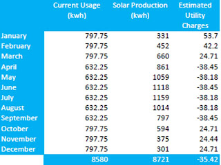
My assumptions were:
One of the problems we have is that our job is not the typical situation that most solar installers face. Most people who get solar don't have any in the first place, and so the solar installer can take a year's worth of PG&E electrical usage data and come up with a good estimate about how the homeowner can eliminate 80% of their PG&E bill by installing solar. At which point, the homeowner is thrilled because the estimate shows them paying PG&E far less. In our case, we already have a solar PV system, so our bill tells the installer little about our electrical use. We still draw about 2000 kwh from the gird, but we pay nothing for that power because PG&E credits us around 3x for power generated on summer afternoons what we pay for power at night, when we are recharging our converted plug-in Prius, and in the winter, when we have lots of lights on and the furnace runs. We never use up the surplus credit, though we have been coming closer since we converted our 2008 Prius to a plug-in hybrid. We also are also primarily interested in completely offsetting the carbon footprint from our electricity usage, not in eliminating or reducing our electric bill, though of course that should follow if we completely offset the electricity usage.
In addition, we are having some new electric appliances installed, and are planning on buying a Nissan Leaf electric car next year. So we need somehow to plan a system that will offset our current grid draw and, in addition, offset the usage from the new appliances and the electric car if we want to eliminate our carbon footprint. Estimating the usage from the appliances is straightforward, but with the car, the electrical usage is likely to be somewhat more unpredictable. However, I came up with the following projected usage requiring offset in addition to the power provided by our current 2.5 kw system:
- 2000 kwh/year - current grid draw
- 360 kwh/year - HRV system used for 6 months in winter when the windows are closed, 24 hours per day
- 633 kwh/year - on-demand electric backup hot water heater. This was calculated by using the historical energy use from our gas-fired hot water heater, correcting for the (in)efficiency of gas-fired tank hot water heaters, and assuming that the backup heater would be needed for 6 months in winter.
- 2000 kwh/year - Nissan Leaf charging. This was calculated assuming 8,000 miles per year at 0.25 kwh/mile. We typically drive our commuter/around-town car about 8,000 miles per year and 0.25 kwh/mile is a standard figure that a reasonably aerodynamic electric car should achieve (it is slightly more than what Nissan assumes, since the Leaf has a 24 kwh battery and is supposed to get around 100 miles on a charge).
My original plan was to add a 30% margin to that to allow for power usage growth in the future. For example, if we revisit the decision not to install a geothermal heat pump, or even maybe go for an air source heat pump, we would then remain carbon neutral without having to install new panels. However, I found out near the end of the design process that PG&E won't allow solar installers to put in more panels than will completely offset the homeowner's electricity use, without good reason. Theoretically, this would not have allowed us to offset the new appliances or the Nissan Leaf because they weren't on our bill last year. REC and the other companies bidding on the contract kept sending bids for 18 panels, or 26 panels, until finally the REC engineer explained the problem. When I told them about our situation, the REC engineer accepted my explanation - that we were buying an electric car - as sufficient justification for a larger system. However, they would not let me include a 30% margin. This is unfortunate, because I was planning to offset the carbon generated by our gas hydronic furnace, gas stove, and new gas fireplace from the portion of the 30% margin that we didn't use. I guess we will just have to continue to buy carbon credits for that, as we are doing right now.
I also originally requested Sunpower E19 modules which generate 315 watts/panel, thinking that more watts per panel would reduce the number of panels and therefore the amount of space on my roof taken up by the PV system. However, Christine pointed out that the E19 was actually larger than standard modules, around 10" wider, though the same length. So, in effect, we would end up using about the same amount of roof space with the E19 as with a set of standard panels that generate 235 watts/panel, the maximum currently available in a standard-sized residential panel. REC also advised not to go with Sunpower, since they are a name brand and they charge extra for the brand. They instead recommended the Kyocera 235 watt module, the KD235GX-LFB. This model produces exactly the same amount of power as the Sunpower E18 series (which is standard sized) but is cheaper.
My original calculations, including the 30% margin, came up with a total system size of 6.85 kw DC. However, I failed to account for shading and losses due to AC conversion. When REC calculated the size of the system, it was 7.050 kw DC without the 30% margin. In either case, the number of panels is 30. As a practical matter, this is probably the maximum amount we can fit on the part of our roof that gets sufficient sun year round. You can see the problem in the picture below, which was screen-copied from the satellite photo of our roof from Google Maps (taken before the solar thermal system was installed on the east roof):

The next decision we needed to make was about inverters. An inverter changes the electric current from DC to 60 Hz AC (usually around 440 volts), which is compatible with the grid. The conversion process is relatively inefficient, losing around 12-15%, which is why REC's design calls for more DC power than my initial estimate. Our old system has a centralized inverter that sits on the side of our house, here you can see it:

When we had the old system installed, centralized inverters were the only technology available. Centralized inverters require the solar panels in each row to be wired up in series. The output side of one panel is connected to the input side of another and the entire system is then manually balanced so that the voltage seen by the inverter is the same for each row. The problem with this design is that shading, dirt, and irregular aging of the panels can cause the voltage from one or two panels in a string to drop, either transiently or permanently. Like a string of Christmas tree lights in which if one light goes out, they all go out, the entire string of panels is then cut out and the system loses power from all the panels in the string. The result is that the system can lose somewhere around 15-20% of total power output during a shading incident or permanently if the problem is due to irregular aging.
Recently, new technology has been developed to alleviate this problem. There are two different approaches:
- Microinverters - rather than having a centralized inverter, each panel has a separate microinverter on the panel and the electricity coming off the panel is AC instead of DC,
- Maximum Power Point (MPP) balancing - the electricity coming off the panels is still DC, but a control unit on the panels adjusts the voltage and current so that the inverter always sees the right combination to maximize power from the array.
MPP balancing systems use a centralized inverter, but each panel has a small control unit on it that measures the voltage and current. The control unit constantly adjusts the voltage and current so that the inverter sees exactly the right combination to maximize the energy generated by the system. The MPP balancing system can also determine whether the panel is experiencing accelerated aging or otherwise needs replacing, and report this through a Web interface (microinverters have this ability too). The capacitors in the control unit don't have to be very large and therefore don't need to be electrolytic. So MPP balancing systems typically have a longer warranty, usually 20 years. Still not the same as panels, but better.
When I was originally considering 315 watt panels, I discovered that nobody made a microinverter which handled more than 230 watts per panel, so I requested an MPP balancing system. Residental MPP balancing systems are not parametrized by the panel power rating but only depend on what the centralized inverter can handle. Tigo is one manufacturer of MPP balancing systems. Because MPP balancing systems are used more in large, commercial PV installations where ease of installation by relatively untrained personnel is not an issue, very few residential installers have much experience with them, so they either won't bid them or they have lots of reasons why such systems aren't as good as microinverters. I requested that Christine call up Tigo and another MPP balancing manufacturer and ask them for recommendations about solar installers that know how to install MPP systems.
After I found out about the increased panel size for the 315 watt panels and decided to go with the smaller 235 watt panels, I briefly considered switching to microinverters. But in addition to the issue of the short warranty, microinverters may have a thermal problem. The temperature under a solar panel in the summer is usually very high, maybe well above 100F. The inversion process itself generates heat, and the electronics become more inefficient as the temperature rises. Since a centralized inverter can be positioned where it is in the shade (as it is on our house), a lower temperature can be maintained. MPP balancing systems therefore have the potential to be more efficient in summer, when the PV system is generating the most energy. Because they don't handle such large amounts of electricity, they don't generate as much heat from the electronics. As a result, I requested that we stick with an MPP balancing system. REC has experience installing Tigo MPP balancing systems, which is another reason why we selected them.
REC's final projection was that the system would offset 101.65% of our electricity use and 90.04% of our bill. It's impossible to offset 100% of the bill because PG&E charges around $7/month for the privilege of connecting up to their system. Here's a table of REC's projections about our power use, solar production, current (actually projected) utility cost without solar, and projected utility cost with solar:

The chart shows that we only need to pay for electricity in January and February. In the other months, only PG&E's connect charge appears. The calculation isn't strictly accurate because the estimated usage is the same for each month. Since we'll only be using the on-demand hot water heater and HRV from October through March, the usage for those months should be higher, while the usage for the months April through September should be correspondingly lower. I recalculated the estimated usage and estimated utility charge with solar and came up with the following table:

My assumptions were:
- The 993 kwh/year usage from the HRV and the backup hot water heater were removed from the summer months and distributed evenly over the winter months,
- The 165.5 kwh/month thereby gained in the summer months were sold to PG&E for $0.28/kwh, the summer afternoon net meter tariff,
- The 165.5 kwh/month used in the winter were bought from PG&E for $0.10/kwh, slightly higher than the current PG&E winter tariff.
Saturday, November 13, 2010
Holes
Work seems to be progressing but mostly in the design space at the moment. The electrician finished up the low voltage wiring and all but one of the new 110V circuits. We have settled on a solar contractor and a rough set of specifications for the solar PV. The contractor is now working on a specific design and a bid. We have requested that the contractor have on-site at all times someone who has worked for the firm for at least one year, so we don't get burned again by an incompetent employee that was hired a few months ago. The insulation bids that were solicited by The Project Manager Who Shall Not Be Named were, as with most of the work he did, inadequate and Paul is re-soliciting based on my feedback. Our 200 amp upgrade request is in with PG&E and we are trying to find out the schedule. Projected completion is beginning of Feburary, but I believe that may stretch out depending on the solar PV installation schedule. But best of all: The Lovely Wife seems to be happy with progress!
I had a moment of concern that the extra 100 amps for our grid connect might not be enough after I found out that the on-demand hot water heater has three heating units, each of which requires 220V/40 amps. That is an enormous amount of power, 8.8 kilowatts, but applied over a very short period of time, maximum 20 minutes for a shower, so the net energy used is less, about 3 kilowatt-hours. The electric car charger only requires one 220V/40 amp circuit, but charges over a period of 6 hours. I did a rough calculation assuming a 440V/100 amp upgrade to the existing grid feed (440V/100 amps), which seems to be fine for our current set of appliances, and it should hand the on-demand water heater, electric car charger, and HRV (the HRV is peanuts, maybe 40 watts maximum).
I also did a short tour of the gutted interior looking for holes. One "feature" of older houses such as ours is the shoddy sealing of exterior penetrations. Here is an example:
 The thin white line you see on the left side of the picture is a 1/4" to 1/2" gap between the dormer flashing and the building frame in the upstairs bathroom. This gap acts as a conduit for warm air to leak out of the building in winter. The fiberglass batt insulation that was in the stud bays here is completely inadequate to stop such leakage.
Gaps also occur between the interior wall space and the living space, as in this picture:
 This picture was taken in the upstairs bathroom where the drywall was removed between the raised downstairs bathroom ceiling and the upstairs bathroom wall. The gray area is the back of the drywall on the light tray above the shower and toilet compartment doors in the downstairs bathroom. The white dust is plaster from drilling when the HRV vent was installed. The thin white line at the bottom is a 1/4" gap where the contractor failed to tape the drywall. This gap now acts as a conduit for smelly air from the bulk of the house to leak into the bathroom when the bathroom ventilation is on.
Another gap has even more serious effects:
 I crawled into the unfinished attic next to the southeast bedroom upstairs where the HRV is now located. This picture was taken at the far end, where the uninsulated bathroom wall terminates the space. What you are looking at in the center of the photo is a large gap under the bedroom floor where the old forced air duct plunges under the floor toward the mechanical room where the old forced air furnace was located. The whitish yellow blob is insulation on the forced air duct. To the left of the gap, the space between the unfinished attic and the floor under the upstairs bedroom (which is over the ceiling of the master bedroom downstairs) is blocked off by a floor joist. But the gap for the forced air duct is completely open, and explains why, on summer nights, the downstairs master bedroom smelled like someone's old hiking boots. We had a pocket door installed in the master bedroom a few years ago. The interior of the pocket door is open into the wall cavity and not sealed. So on summer afternoons, when the upstairs unfinished attic is shaded and cool but the downstairs bedroom is warm, cool smelly air from the unfinished attic enters into the wall through this gap and out the pocket door enclosure.
Here's a gap that is not quite a hole:

This is between the fiberglass window frame and the wood frame of the house. There is no insulation here although the space is sealed on the outside, but this gap acts as a thermal wire, allowing warmth to escape from the house in winter.
The disturbing aspect of these last two examples is that they are in areas where we had contractors work in the 7 years since we owned the house. They are not from the original framing or from work done by previous owners. You would think that, in the 21st century, contractors would have some clue about building science and make sure that the work was up to the latest knowledge at best quality. But most contractors are clueless about how to properly insulate a building. They are still working with knowledge they gained in the 70's when they started working.
Finally, and example of the attitude toward proper insulation in the 70's when our house was built:
 This picture was taken from outside the house, looking into the cavity under the tiled shelf under the living room windows. What you see here is a chunk of fiberglass insulation on the right side and the end of a chunk on the left (obscured by the wood frame). In the middle, is a huge gap, 4-6" wide, where an electrical wire runs and the drywall is visible. It is no wonder the tiles in the living room are icy cold in winter.
The picture is a perfect example of the attitude about proper thermal sealing in California in the the 1970's. It seems to be: "oh, California is such a mild climate and gas is cheap. Let's throw in a couple pieces of insulation here and there to say we did it. No need to do a through job". We saw exactly the same kind of shoddy insulation above our kitchen ceiling when we had a sun tunnel installed a couple years ago.
This example is why I disagree with people such as Matt Golden at Recurve, who claims that there is lots of "low hanging fruit" in energy efficiency. The number of houses that have no insulation at all and can be reinsulated at relatively low cost by drilling through the drywall and injecting blown in cellulose is far exceeded by the number with shoddly installed fiberglass batt insulation like ours. Most houses with no insulation were built before 1970 and there are far fewer of those than were built between, say, 1970 and 1995 or so with shoddily installed insulation. The cost and hassle of reinsulating a house like ours using the existing building technology, as we are finding out, far exceeds what most people are willing to go through.
I had a moment of concern that the extra 100 amps for our grid connect might not be enough after I found out that the on-demand hot water heater has three heating units, each of which requires 220V/40 amps. That is an enormous amount of power, 8.8 kilowatts, but applied over a very short period of time, maximum 20 minutes for a shower, so the net energy used is less, about 3 kilowatt-hours. The electric car charger only requires one 220V/40 amp circuit, but charges over a period of 6 hours. I did a rough calculation assuming a 440V/100 amp upgrade to the existing grid feed (440V/100 amps), which seems to be fine for our current set of appliances, and it should hand the on-demand water heater, electric car charger, and HRV (the HRV is peanuts, maybe 40 watts maximum).
I also did a short tour of the gutted interior looking for holes. One "feature" of older houses such as ours is the shoddy sealing of exterior penetrations. Here is an example:

Gaps also occur between the interior wall space and the living space, as in this picture:

Another gap has even more serious effects:

Here's a gap that is not quite a hole:

This is between the fiberglass window frame and the wood frame of the house. There is no insulation here although the space is sealed on the outside, but this gap acts as a thermal wire, allowing warmth to escape from the house in winter.
The disturbing aspect of these last two examples is that they are in areas where we had contractors work in the 7 years since we owned the house. They are not from the original framing or from work done by previous owners. You would think that, in the 21st century, contractors would have some clue about building science and make sure that the work was up to the latest knowledge at best quality. But most contractors are clueless about how to properly insulate a building. They are still working with knowledge they gained in the 70's when they started working.
Finally, and example of the attitude toward proper insulation in the 70's when our house was built:

The picture is a perfect example of the attitude about proper thermal sealing in California in the the 1970's. It seems to be: "oh, California is such a mild climate and gas is cheap. Let's throw in a couple pieces of insulation here and there to say we did it. No need to do a through job". We saw exactly the same kind of shoddy insulation above our kitchen ceiling when we had a sun tunnel installed a couple years ago.
This example is why I disagree with people such as Matt Golden at Recurve, who claims that there is lots of "low hanging fruit" in energy efficiency. The number of houses that have no insulation at all and can be reinsulated at relatively low cost by drilling through the drywall and injecting blown in cellulose is far exceeded by the number with shoddly installed fiberglass batt insulation like ours. Most houses with no insulation were built before 1970 and there are far fewer of those than were built between, say, 1970 and 1995 or so with shoddily installed insulation. The cost and hassle of reinsulating a house like ours using the existing building technology, as we are finding out, far exceeds what most people are willing to go through.
Sunday, November 7, 2010
HRV, On-Demand Water Heater, and More!
I arrived back home after 2 weeks off-line on vacation last Sunday, and briefly checked out progress on the job. Then I immediately flew to Washington, DC, early the next day for a conference, coming home on Thurs. A lot has been done in the 2 weeks I was gone, more than in the previous 2 months. Today, I finally had time to poke around in more detail. Here's what's been happening.
Mold
Fiberglass batting is not air proof, air can leak through. When our roof was replaced in 2003, the builder did not install any ventilation under the plywood decking as buildingscience.com recommends. Ventilation allows the warm, moist air from inside to vent to the outside, but also of course results in energy loss through the thermal envelope. So in many places, warm indoor air came up against the cold roof decking in winter and condensation accumulated on the plywood. When the water remains more than 24 hours, mold will grow. We had many places on the decking where mold was growing, especially along the ridge in the hallway, since that is the highest spot in the house and is naturally where the hot air accumulates. There were also a couple places on the south side of the house with mold on studs and siding. Since I have a mold allergy (one of the many reasons why we are doing this remodel), I insisted that the mold be removed. We had a mold remediation company come in and treat the mold. The closed cell foam insulation that we are having installed doesn't allow air to penetrate, so it can be sprayed directly on the roof decking and siding to seal against air leakage.
Fireplace
Before we started the remodel, we had in our living room an old pellet stove without any thermostat that needed to be started by hand. I really wanted a newer model with thermostat and automatic starting, but Santa Clara County has a ban on wood burning appliances due to pollution during winter inversions. So we instead opted for a 90% AFUE gas Empire Comfort Mantis fireplace. This is about the most efficient gas fireplace that you can get. It has a condensing firebox that retrieves the heat of condensation from the steam formed by combustion, and takes combustion air from outside rather than within the home. The only downside is that it won't work when the grid is down because the outside venting requires a fan. But neither would a pellet stove, since it requires electricity for ignition and the screw that retrieves the pellet from the hopper.
On Fri., they installed the fireplace. Here's what it looks like without the copper surround:

and here is what the plumbing looks like coming out the back:

One pipe is for the combustion air intake, the other for the combustion gases exhaust. Unlike a lower efficiency furnace/fireplace, the combustion gases are not hot enough to simply float up a chimney and water would also condense out on a metal pipe, so a normal chimney/flue can't be used.
Structural Reinforcement
Another reason why we started this work was because the drywall along the ridge line in the hallway cathedral ceiling was cracking. Not just in small areas, a big gap opened up right along the ridge line from the front bedroom to the middle skylight and it would expand and contract depending on the temperature, raining down little bits of plaster when the temperature rose. Fixing this has turned out to be an enormous problem, and has been responsible for holding up the job for at least a month and a half. We have gone through two structural engineers trying to get some kind of solution that would immobilize the roof enough to prevent future cracking without having to take the roof off and put in new trusses. The basic problem is that the roof beams installed originally were not sturdy enough to support the weight of the skylights and the plywood decking without twisting some. Originally, the roof was wood shake shingles which are lighter, but we replaced it with composite shingles because they last longer, which required the plywood decking. This increased the weight of the roof. But even without the decking, the original roof supports are really not sturdy enough to support the full weight of the skylights - some of our neighbors with the same model house have a similar problem with cracking. It does not mean that the roof will collapse in a major earthquake, just that it is not stable against thermal expansion and minor movement.
The Project Manager Who Shall Not Be Named had the framers install metal plates at the joints but that was insufficient for some of the forces. So the new structural engineer and Paul came up with a series of what look like 10x4's that run up to the ridge beam and transfer some of the load onto the rafters further down:


Here you can see how the beam runs from the skylight, on the left, down along the rafters, on the right, distributing the weight of the skylight more evenly along the roof. The new beams are bolted to the rafters with heavy bolts:

Paul says that the beams will not likely prevent cracking during an earthquake but they will prevent the twisting with temperature and random minor movement which seemed to have caused the original problem.
HRV
The HRV system has been partially installed. We have two HRV units, one in the attic above the garage and one in a chase next to the east side upstairs bedroom. Here's a picture of the one in the chase:

The HRV unit is the Fantek SH704. The hard metal pipe running across above the unit is the existing bathroom ventilation from the downstairs master suite bath. The foil clad soft ducts on the left and the fiberglass clad ducts on the right are the new HRV ducting. The metal bar across the top is the mounting frame for the HRV.
When I first saw the metal bar, I was a bit upset. We had agreed to hang the HRV from wires in order to avoid transferring vibration to the house frame. After all, this unit is right above the master bedroom and next to another bedroom (which we use as The Lovely Wife's sewing studio) . It looked as if they had simply bolted the metal frame to the ceiling rafters and the HRV to the metal frame. However a closer inspection showed that the HRV apparently has a kind of shock absorber on it:

I think a rubber grommet is missing and must be installed yet in the shock absorber. So I'm willing to try it out to see whether or not there is any vibration.
Some details still must be worked out. The attic HRV, on the other side of the house, needs its humidity drain installed somewhere, and I'd like it to go into the new downspout that will be on that side of the house. And the intake and outlet vents on the chase HRV are uncomfortably close, and also close to the master bath venting:

I've asked Paul if we could locate the intake vent further up toward the roof peak where it it is less likely to draw in stale air from one of the exhaust ports. The new chase we installed running from the HRV chase to the hall exhaust vent seems to have enough room that one could run a second duct, depending on how large the duct is. The exterior venting has yet to be determined on the front side for the attic HRV. I've requested that they vent out where the existing attic vent is located, and vent in from the side of the garage. Not sure if they can do this, though, maybe higher on the attic wall would be better.
The interior ducting for the HRV looks like this:

Here the ducting runs in the chase next to the upstairs bedroom. An insulation guy is going to have to climb back in there to insulate the stud bays above the master bedroom and the back of the bathroom wall. It's a tight fit, I climbed back in there myself today. But because the ducts are flexible, you can shove them around, unlike standard forced air ducting. So I think it should be possible.
This next picture shows the chase in the front bedroom closet where the exhaust duct runs from the attic HRV to the exhaust vent in the hallway:

The framer put this chase in so we could run the HRV duct, and a similar one in the east side upstairs bedroom. The attic HRV draws in warm, stale air from the top of the cathedral hallway through the hall vent into this duct and exhaust it, after transferring the heat to fresh, incoming air. The vent cover for the HRV looks like this:

I've requested from Paul if we could get vent covers that look a little less intrusive. White on a colored wall is just too noticeable for my tastes.
On-Demand Electric Hot Water
The framer put in a closet above the upstairs bathroom door for the on-demand hot water heater and also for storage. The Tempra 20 Steibel-Eltron on-demand hot water heater was also installed, though it can't be actually hooked up to the power line until PG&E comes and installs 200 amp service:

Notice the lack of any venting? That is one nice thing about an electric hot water heater as opposed to gas. Because there is no combustion, it doesn't need venting, it's just another electric appliance like the washer or refrigerator. So we can use this closet like any other closet, for storage. It just happens to have a hot water heater in the back.
I checked out how the plumber fitted it into the solar hot water plumbing, and I am not quite sure if I understand. I've asked Paul to check. It should be in series with the solar plumbing, with the hot side of the solar tank running directly up to the on-demand heater, and the hot side of the on-demand heater running to the mixing valve downstairs and then into the domestic supply. This allows the hot water from the solar tank to rise up to the on-demand heater between use, eliminating a gout of cold water that enters the on-demand heater when a hot water tap is turned on, which could cause the on-demand heater to fire for a couple seconds till the flow from the solar tank hits it.
Some people, like Allison here at the energyvanguard.com, don't seem to like on-demand electric hot water heaters. I suppose, if they are not just being used as a backup to a solar thermal hot water system, they could be a problem, since they do use large amounts of electricity, especially if they need to heat the water from 60 degrees F or so to 120 degrees F. But when they are being used as backup, the incoming water is rarely below 100 degrees F and in summer, they won't be used at all. As my previous blog post showed, on-demand electric backup for solar becomes more carbon efficient than gas at some point *if* (and this is a big if) the grid is migrating to non-carbon energy sources. Of course, if you are offsetting the electricity use with home solar PV, as we are planning to do, then on-demand electric backup becomes essentially carbon free. It is also possible to offset a gas on-demand backup with solar PV too, but a gas on-demand heater then requires complex venting.
Next up: PG&E installation of the new 200 amp service, a decision on the solar PV installation and selection of an insulation contractor!
Subscribe to:
Posts (Atom)


